January - December 2026
Now into Feb 26 and the accidental omission of the bump stop
rubber under the top strut cup has been rectified by dismantling
it and popping said item over the shock absorber rod. The rubber
gaiter has also been attached to the top strut cup, albeit only
with a cable tie because I could not find a big enough jubilee
clip, unfortunately. I *think* it will be alright!
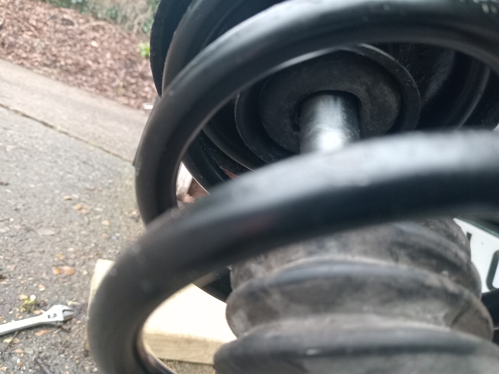
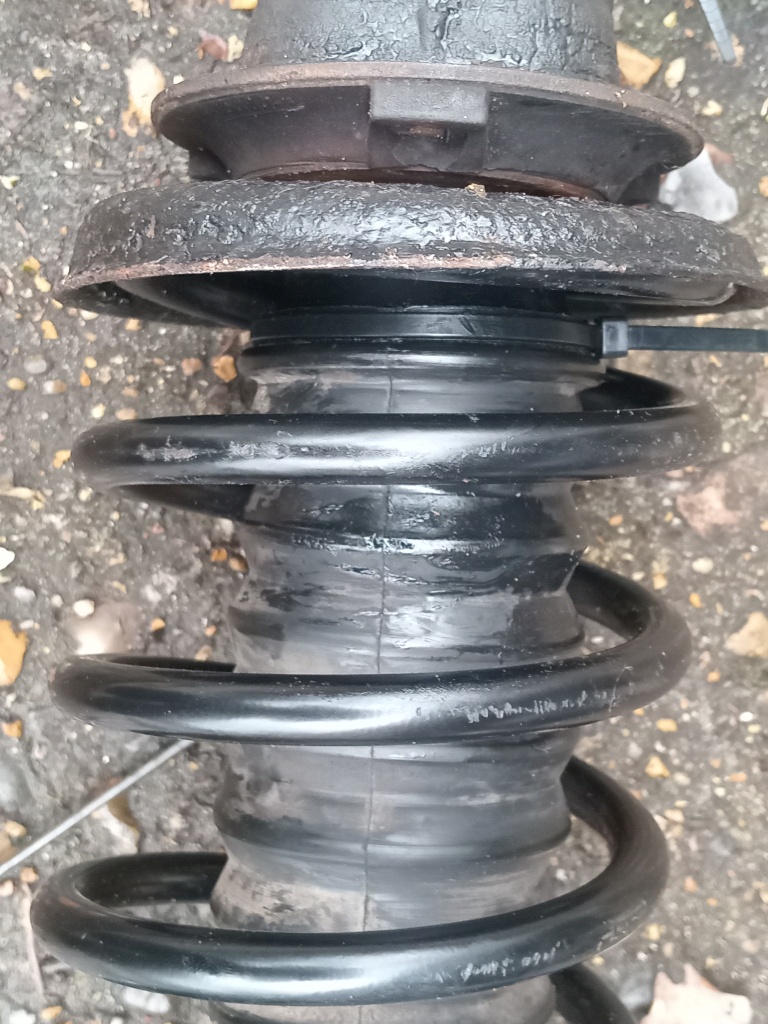
Anyway the strut has been refitted to Blue Bess and various nuts and bolts recycled and tightened-up to the correct torque with thread-lock used for good measure, too.
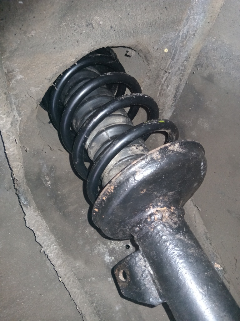
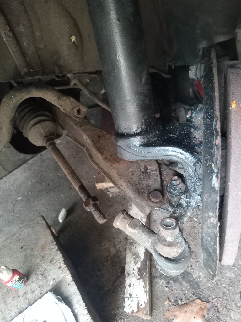
However, I am struggling with obtaining the correct sway bar
link due to a confusion over which is the left- and right-hand
side of the car. Needless to say, I am sure it will be sorted
out in the end.
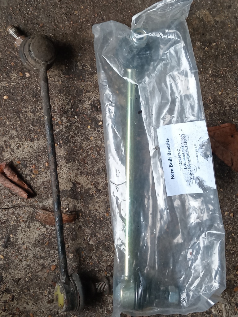
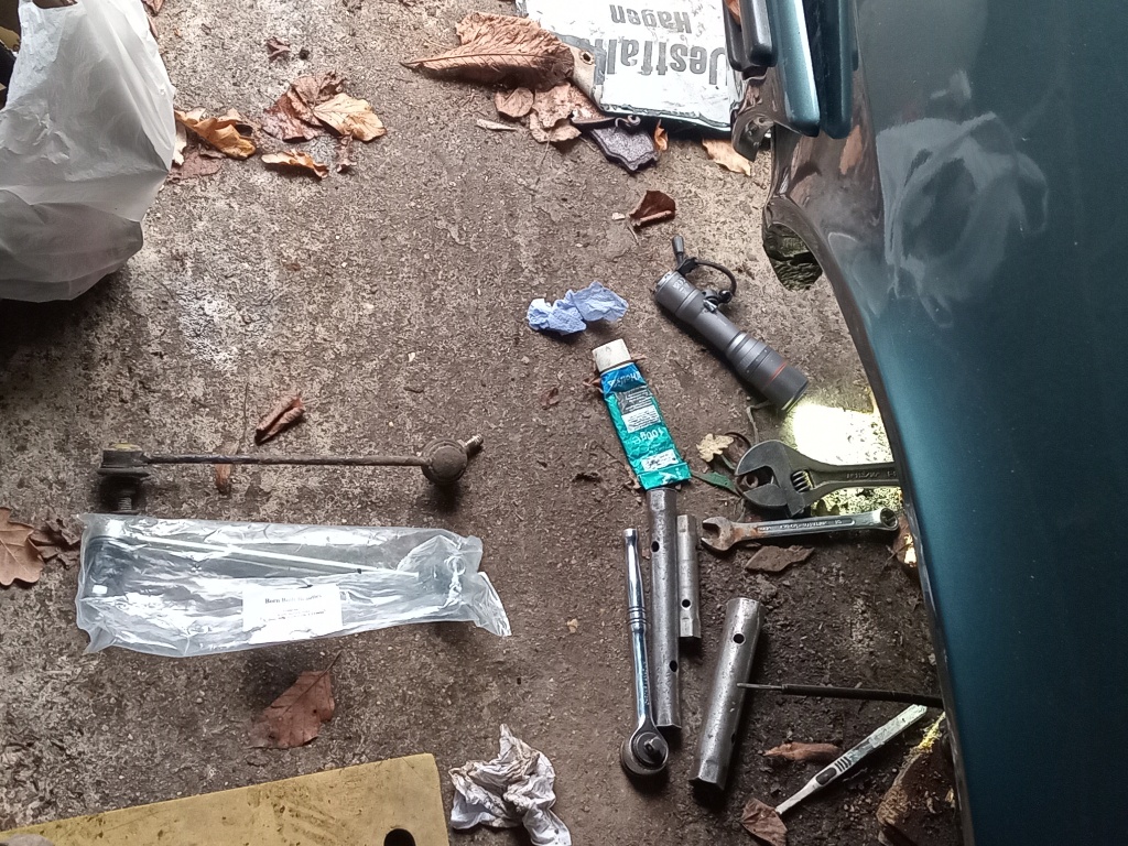
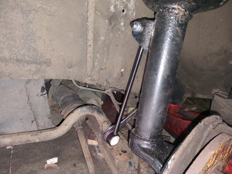
After sorting out the correct sway bar or drop link, we are
going back together again.
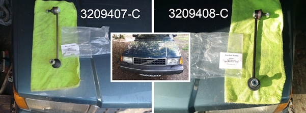
For reference, the two part numbers for the sway bar from Born
Built Beauts are shown below, hopefully to avoid similar
confusion in future.
So we attempt to replace the brake caliper but could not compress the piston back in again to fit newer pads so that one has gone off to the spares shop to be refurbished again, or even replaced - who knows what the future holds for us?
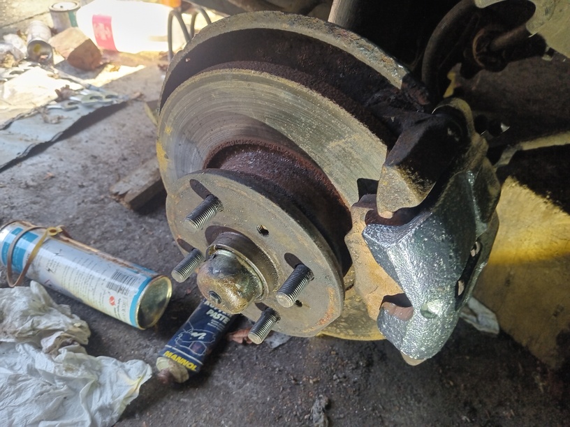
On the other side, the caliper is removed and tested to see if that one is OK and indeed it is, so it is refitted with newer pads as the old ones were down to the last mm of material. The back plate is a bit rusty but I think it will hold for another year or two, partly because I do not fancy replacing it with another 11" pizza pan at the moment, as that would mean splitting the hub. Anyway better pads are fitted and various things coated with waxoyl and copper grease is applied in the usual places so now we are just waiting for the replacement unit on the other side.
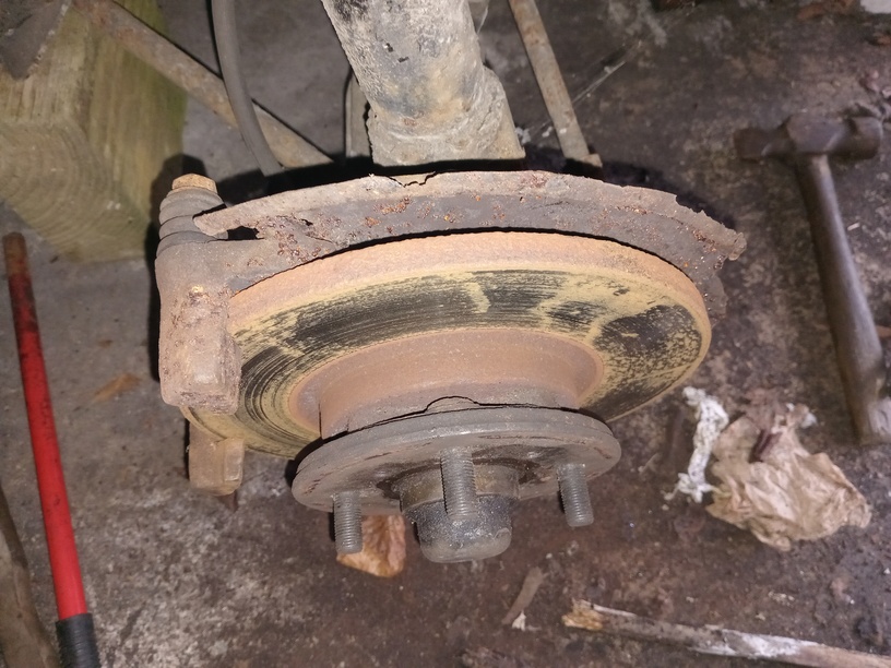
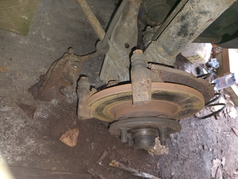
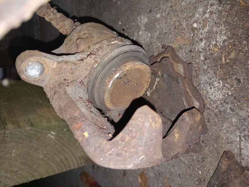
The bleed nipples on both calipers have not seized-up or snapped-off and the brake disks on both sides clean up reasonably well with a wire brush and some emery paper, so what could be better?
Now into April 2026 and a caliper has been procured locally and the brake pads replaced with those that came with the car way back in 2004! Everything has been put back together except that the steering tie rod has not been tightened because the tracking has not been set, yet.
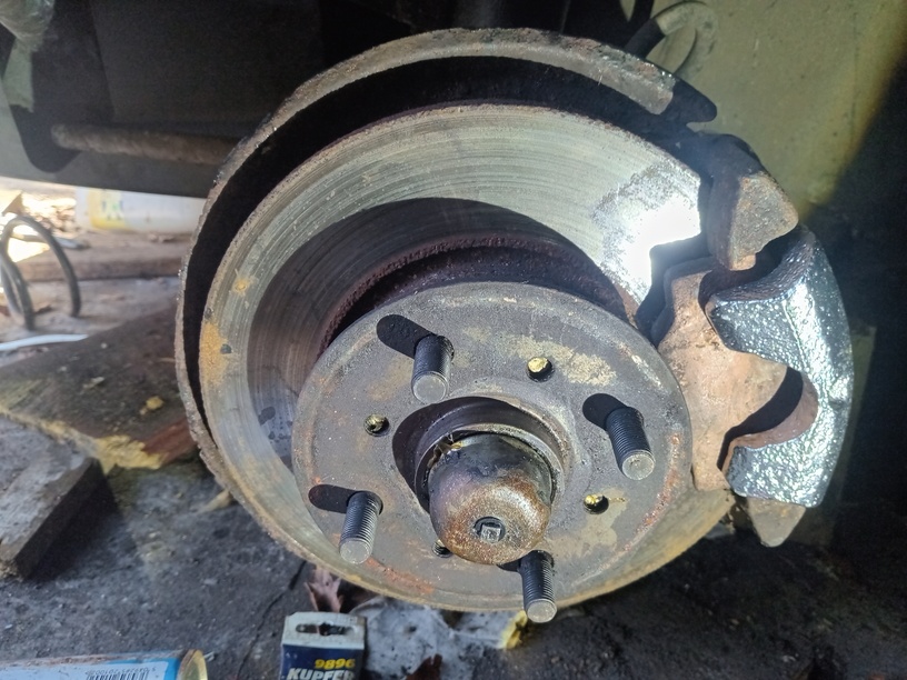
On attempting to refill the brakes with fluid, I find that the rear driver's side brake cylinder is seized but the other side is OK, so only one side needs replacing. Its going a bit slow joe crow this year as we're already into early May 2026 by now, but the cylinder has been replaced anew.
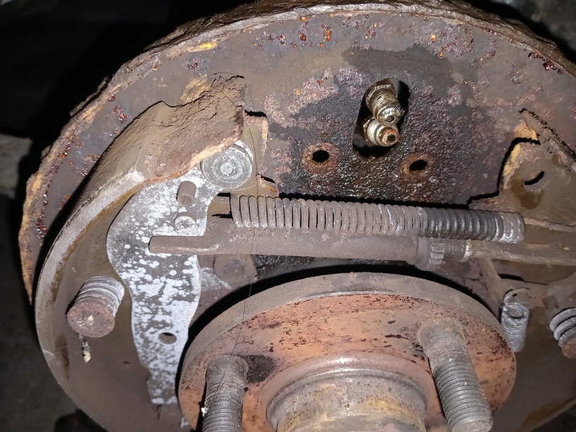
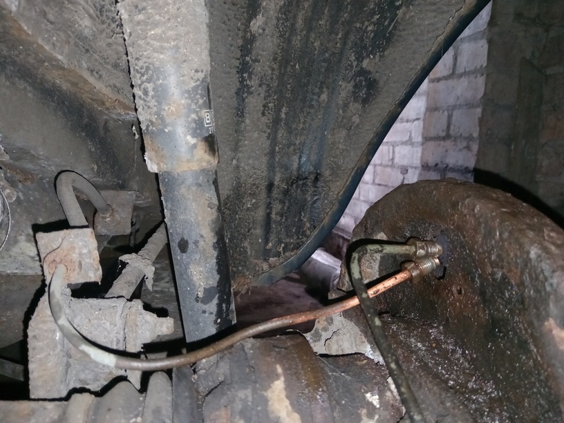
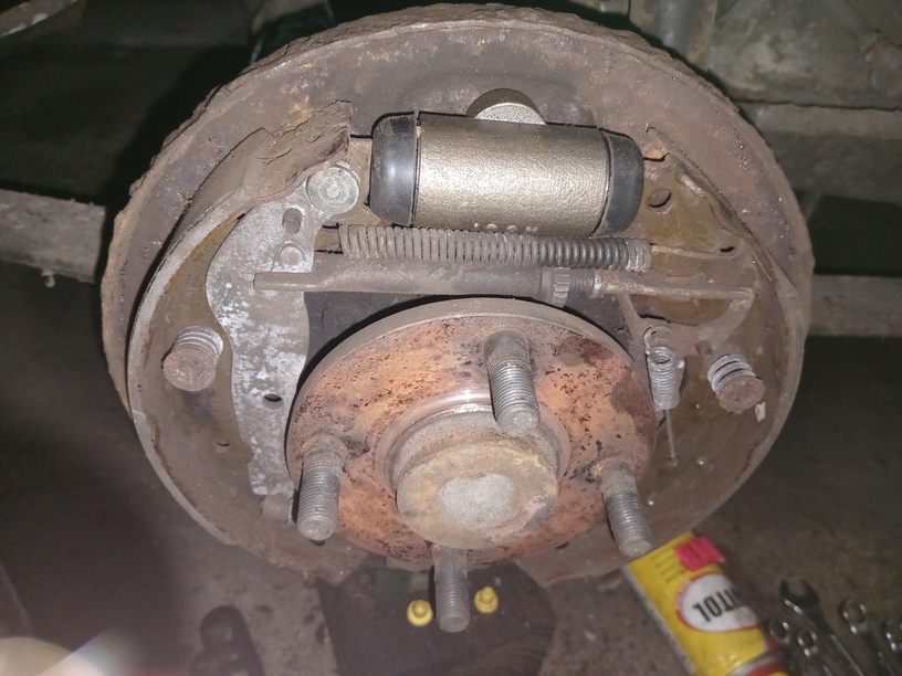
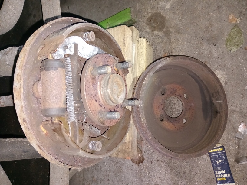
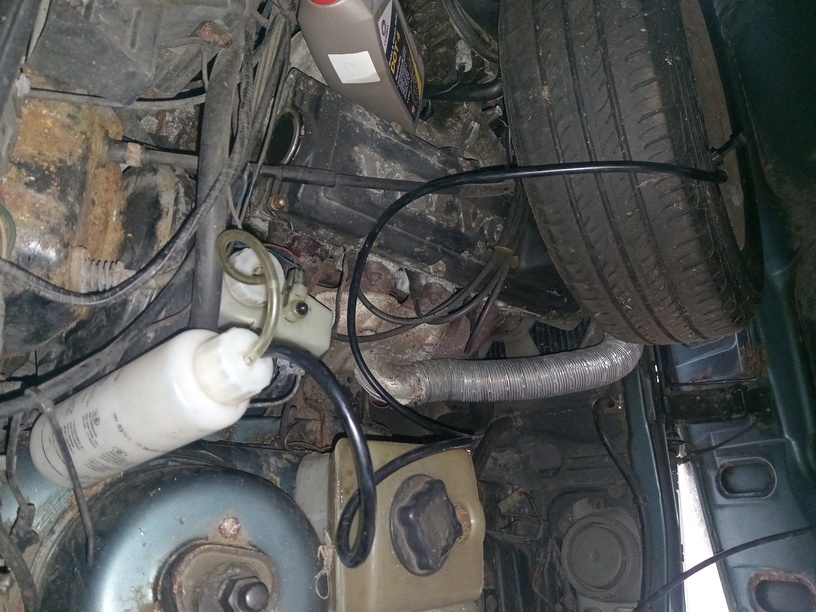
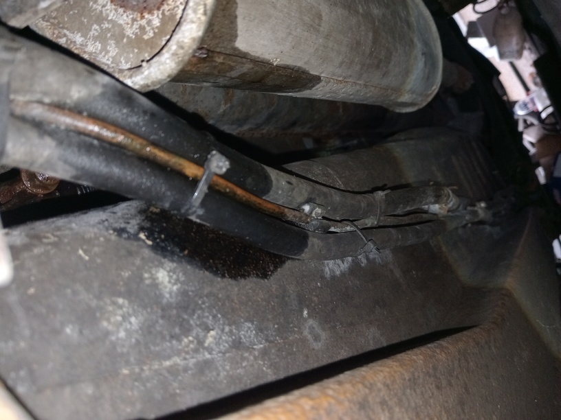
The brakes were then successfully bled with the easy-bleed kit but try as I might, I cannot get the new rear brake cylinder to fill up and adjust itself, bah humbug. This is going to need starting the engine to get the servo going but, there's a big hitch because I spotted that the fuel hose had been re-routed at some point in the last 15 years so that it was no longer in the chassis leg. Instead it had been cable-tied to the copper brake pipe running from front to back and was therefore about 1 cm from the front exhaust silencer. This would therefore account for all of my fuel evaporation issues which led me to install multiple electric and mechanical pumps and other paraphernalia over the last decade. Never mind, we will sort it out but it is embarrassing that it took me that long to notice, not arf.
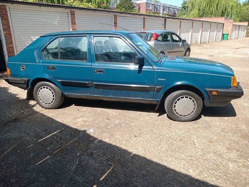
Anyway, now at the end of May 2026 and its time to renew the insurance on my only running 340, Deep Blue, and this requires that some new photos are taken. Here they are.
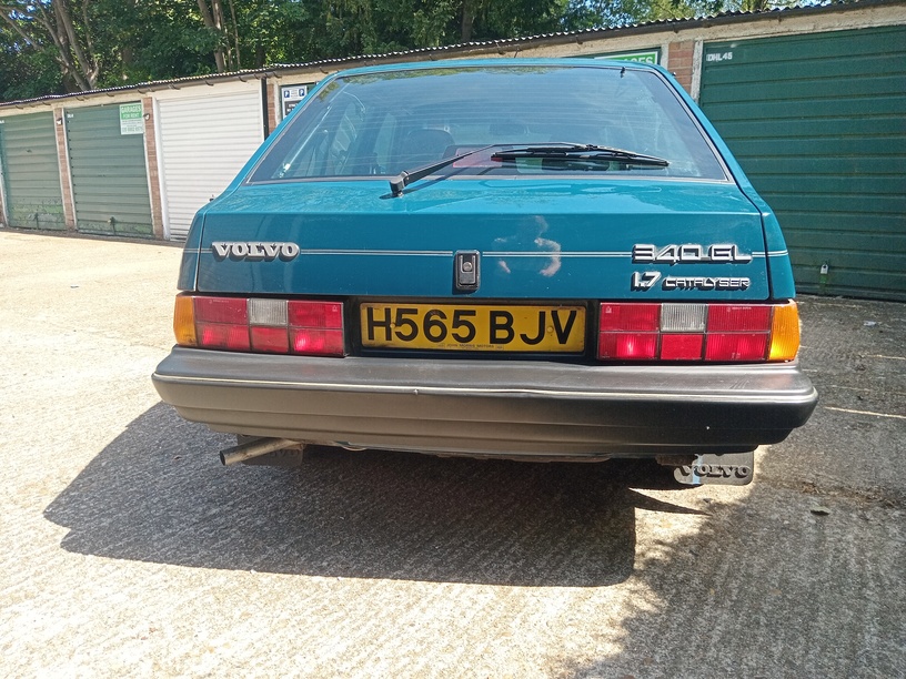
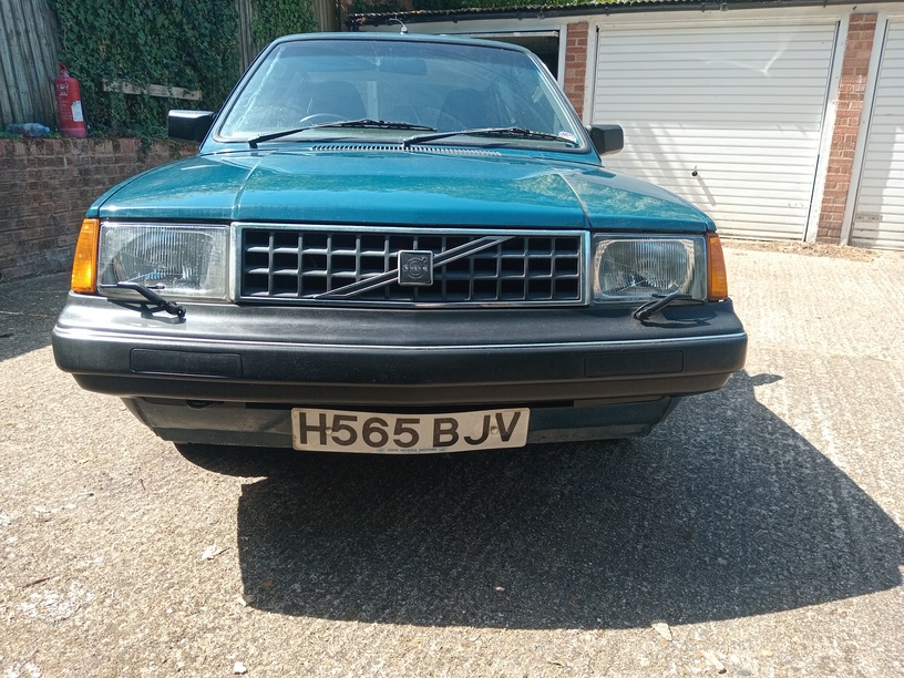
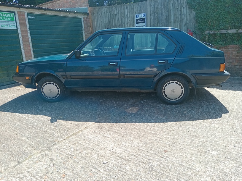
In late May the removal of the old fuel hoses begins with their detachment from the fuel tank and a couple of new nylon hoses are procured from the internet. They have 8 mm and 6 mm external diameters and 6 mm and 4 mm internal diameters, respectively. A psychedelic blue braided nylon sleeve is acquired, too, to help prevent them from rattling against surfaces that might wear them away. I have also identified the hole in the chassis leg that the new hoses have to be pushed through from the engine bay (bottom right photo).
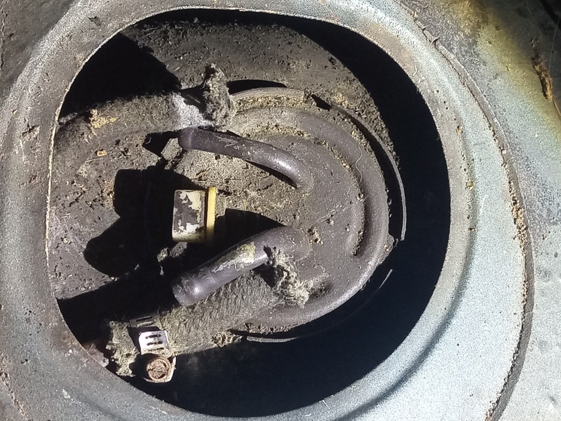
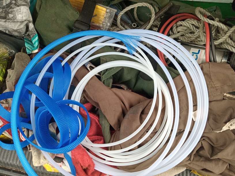
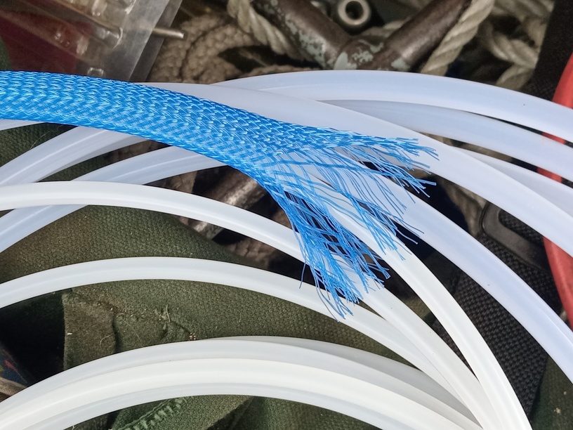
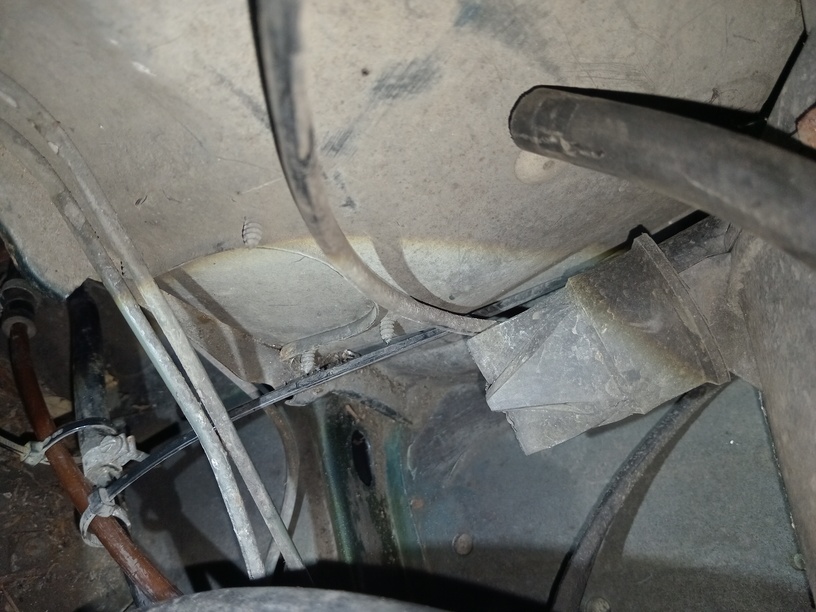
The new hoses are taped together at one end, are pushed through the box section from the front and they duly reappear at the other end. A bit more fiddling about allows them to thread over the torque tube and over the tank so that they reach the fuel sender under the back seat.
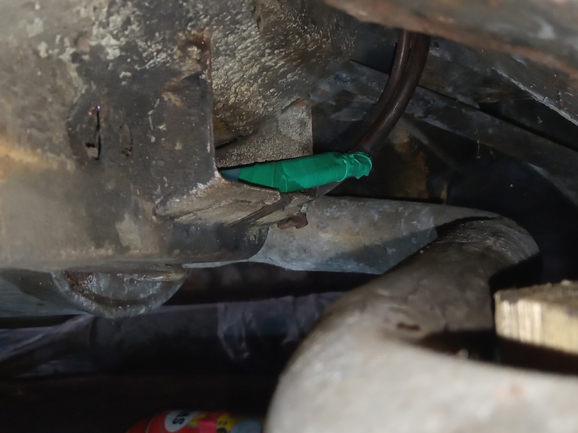
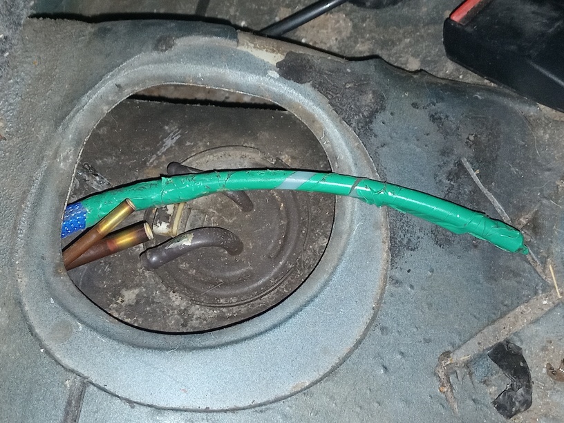
After some trimming to get them to line up with the fuel sender connections, some home-brewed olives are inserted into them to prevent them from collapsing when the jubilee clips are done up. These olives are made from a telescopic radio aerial and from sawn-off and milled-down rivet sleeves. I did order some proper ones but they were a bit shorter than I hoped and I made a bloomer with one of them by ordering the wrong size. Home brew saves the day.
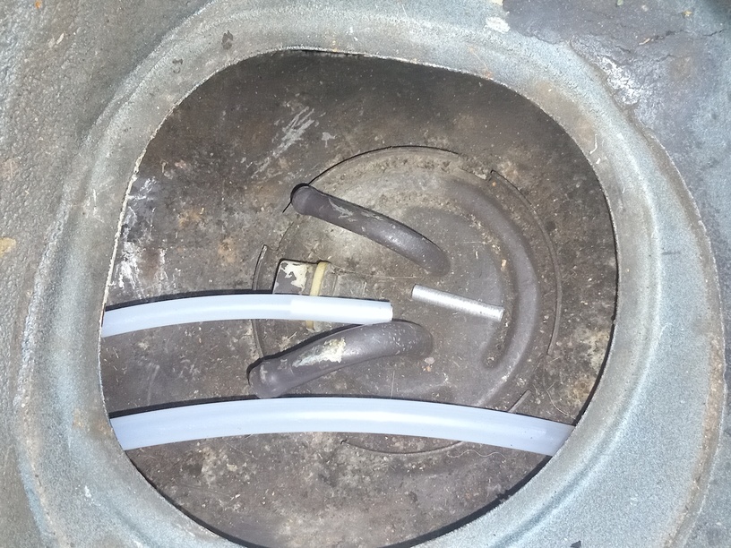
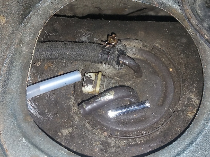
Everything gets reconnected but I realise that the pipes are pressing against quite sharp bits of metal around the fuel tank so wherever it looks like they could wear, I fit a bit of rubber hose to try to protect them.
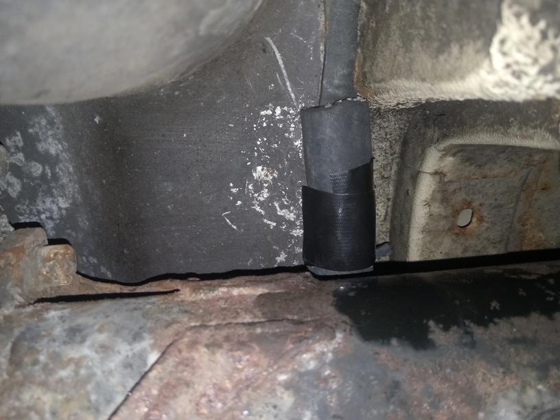
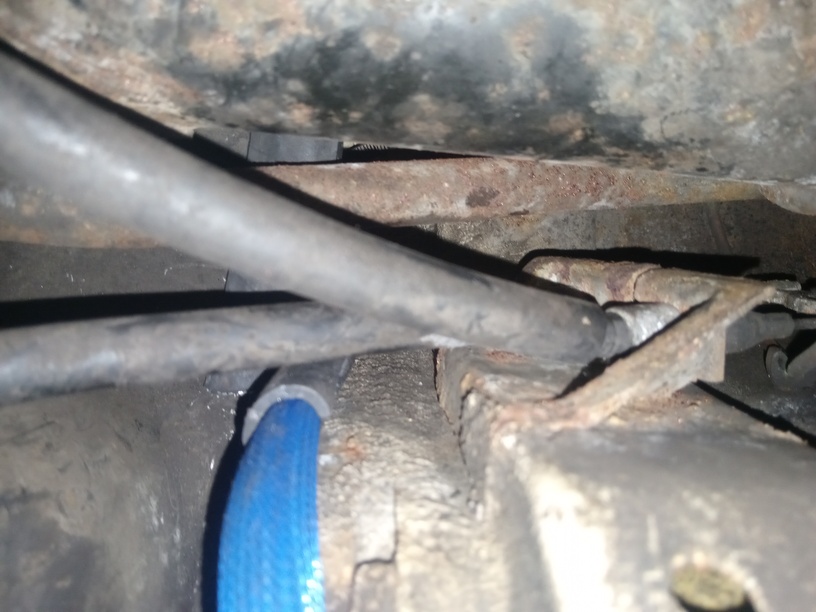
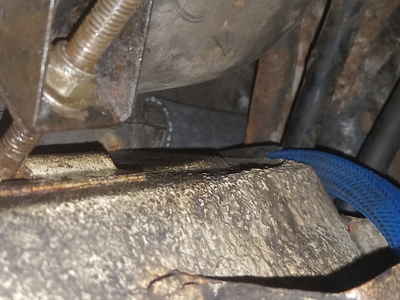
This allows the fairly decrepid old hoses to be removed and the new ones connected at the engine end by around the middle of June 2026. The car then actually starts and runs well, which can't be a bad thing. The rear brakes self-adjust fine and are given another quick bleed to be sure the air has all been expelled.
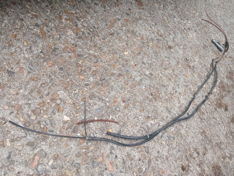
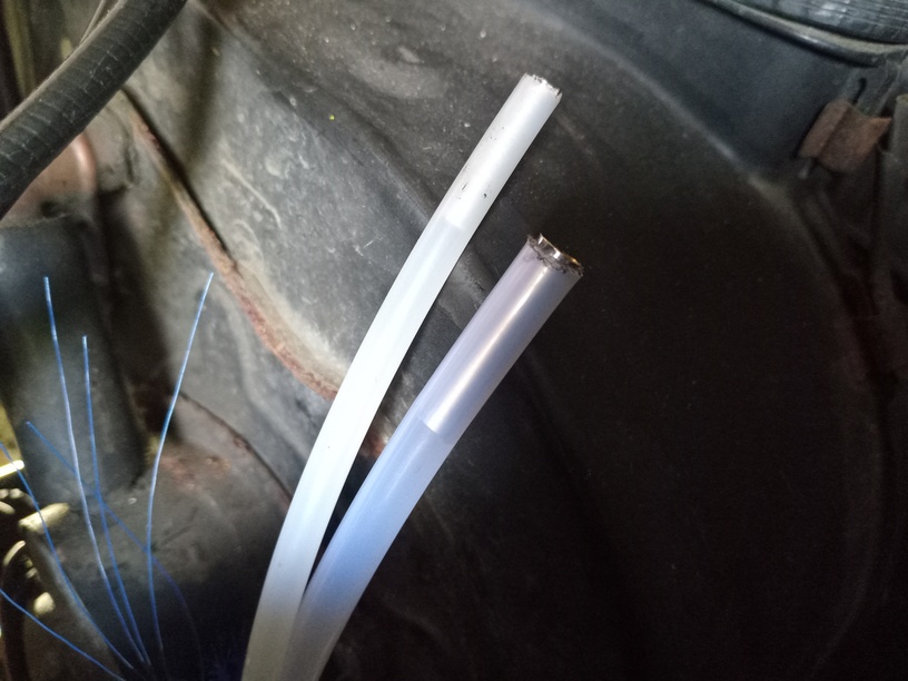
We're now into early July 2026 and its time to replace the dodgy old hose connecting the two halves of the tank, so the tank is drained of petrol and the hose is replaced, with a bit of psychedelic blue braiding to protect it (not). Some waxoyling in that area is done, too.
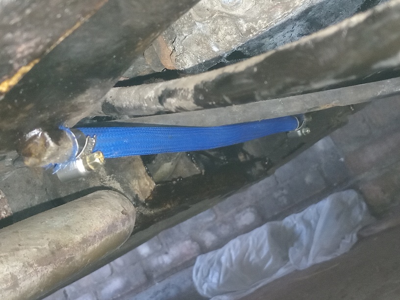
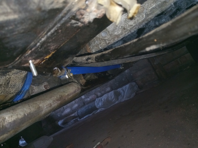
So now it is time to think about what more needs to be done in this area. The heat shield has been spruced up a bit and repainted but before refitting it, etc, I am hoping to see if I can get the gear lever to tighten up a bit which maybe due to something missing at its base. Time will tell.
So, the Summer moves on and is incredibly hot which pretty much puts a stop to my motivation to do things to the old cars, at this great age but come early September 2026, there is some pressure to get things ready for the Volvo 300 Mania annual meeting. Hence Deep Blue is cleaned up a bit, road-tested and put in for the MOT test which she passes with flying colours, by some miracle. I then decide that because the meeting is a fairly major distance away (Derby), I should make the indicator warning lights more audible than they are, the old beeper having pegged out in no time at all really. Hence one of these blue boxes is procured from the internet and fitted. A bit of wire-swapping was needed to get it to work, as can be seen below, and because it is so loud (it is intended for a tractor) it has to be wrapped in a few socks, or the whole neighbourhood can hear it in action. There is a good chance that this will be a solution, so another unit is procured for the 360, to be fitted at some stage in the distant future.


Meanwhile the expansion tank on the everyday Ford Focus gives up the ghost and is replaced temporarily by a spare unit from a 340. More importantly, Deep Blue makes it to the show in mid Sept 2027, as can be seen below. There is a picture of someone's mint red GLT engine thrown in for good measure, too.


It turned out to be a great day with lots to see but the journey back was a bit spooky because the alternator started playing up (battery light came on and went off a few times) and after stopping and convincing myself that it was alright, I continued on my way, but with the headlights on, the load was just too much for it so it died on the M1 at Rugby, duh. Fortunately there was just enough battery to give me enough sparks to get to one of the smart laybys where a call from the emergency phone had the AA sent on its way. The AA man put on a new battery and sprayed some WD40 into the alternator and we were on our way again. I am in the relay scheme so he insisted on following me back to London in case it went again. No complaints.
So we definitely have a dodgy alternator issue which needs looking at over the next few months. The thing is that I have a new 1.4 alternator in the roof and there is a thought in my mind that I can use it on the 1.7, but will it work?


The most obvious difference between the 1.4 and 1.7 alternators is the pulley, so the old pulley is fitted to the new alternator as shown below. The 1.4 alternator is a Valeo A13N64 (40 Amps) whereas the 1.7 one is an A13N120 (60 Amps). I am sure 40 Amps is enough for Deep Blue so it will do.


I had to do a bit of small-spanner work to turn the rear bracket round so that the plug connection is as the top, although I imagine that it is not necessary for it to be there. A big problem then leers its ugly head which is that it does not fit to the car because the 1.7 brackets are slightly different. All sorts of creative thinking and a bit of filing on one of the brackets still does not allow it to fit.


My next attempt involved making a hybrid alternator with the new innards from the 1.4 alternator and the outer brackets from the old 1.7 unit. A bit of heavy hammer work was needed to get the old front bracket off the 1.7 unit but as you can see we are in alternator heaven here. The 1.7 rear bracket has a rubber cushion which I am pleased to borrow for use on the new alternator, too, as it has a wider drive belt.


Thus a hybrid alternator is made with 1.7 brackets, etc, and fitted to Deep Blue but, alas, it still does not work. Now this gets me thinking back to when I bought the 1.4 alternator about 20 years ago and I remember it was suspiciously cheap at about £25, so maybe I bought a dud? It won't be the first time, eh. Anyway this is all getting sufficiently desperate that on finding the local spares shop has a 1.7 alternator for £60, I just decide to get it with the intention of fitting it and just forgetting the whole thing.


Niggle, niggle, niggle, my mind niggles away at these issues, so when the non-working 1.4 unit is removed, I can't help thinking about why it doesn't work. I think it looks too good to confine to the scrap metal pile, so lets get it apart and see if we can find what it wrong with it. After removing the regulator, use of a meter shows that the slip rings are not electrically connected, so the hunt is on to see if the breakage can be found and repaired. If the break is in the coil, then we have no hope but if it is somewhere accessible, then we have a chance. An enthusiastic cat is recruited to devise a bearing puller made from lolly sticks which allows the rotor to be removed from its rear bearing without risk of any damage to the slip rings.


Prodding around with the test meter shows that we have a soldered joint on the slip ring assembly which has gone dry, i.e. lost connectivity. A bit of cleaning up in that area and a dash of new solder (shown above right) has the problem solved for us. The soldered connections to the slip rings are then given a coat of araldite glue and painted with enamel.


We're now into early October 2026 and everything goes back together, the unit is fitted to the car and found to be working wonderfully.


So our hybrid alternator is now working perfectly on Deep Blue, we have a new one as a spare and everything is looking good, but there are niggles and more niggles in my mind from alternator issues still to be resolved, mainly because the alternator bug has bitten and I am thinking if anything else useful can be done in the alternator department given that there are two other 300-series cars which probably need new alternators, too, or will do soon!! What was interesting was seeing the brushes in the old unit after 120k miles.


Red Ness has done 101k miles and I also have acquired a spare 1.7 unit that needs new brushes and slip rings. It suddenly becomes interesting to see if I can dismantle the spare 1.7 unit and replace the regulator unit and the slip rings. Of course the regulator unit with the brushes in it can be replaced without too much hassle. The big question is the slip rings as that is something I have not tackled before!
Anyway, the plan in the short term is to try to refurb the spare 1.7 alternator so it starts to be taken apart, firstly with the regulator being removed and then the rotor, using the cat's bearing puller method as before, however the bearing remains attached to the shaft this time!


Hence, A proper bearing puller is then used to remove it, thereby freeing-up the slips rings for removal.


The slip rings and their plastic mounting were cut off carefully with a Dremel mini-disk cutter and the splines for holding it to the shaft can be seen on the below left. A new slip ring unit was slotted on by gentle tapping and the ends of the wire forming the electromagnet windings were bared for wrapping around and soldering to the contacts with proper (in my view anyway) leaded solder. Unfortunately, I forgot to photograph the soldered joints and the araldite used to cover them, as well as the final coat of enamel paint.


Everything is put back together with the aim of testing it on some sort of home-made rig, using a 12V supply or old car battery and a hand-drill to spin the rotor, all of which fails miserably, although the connectivity of the coil is confirmed with a multimeter. This gets me thinking that its about time to get Red Ness running again and maybe to use here engine bay as the test bed for the home-refurbished alternator. Hence, after a bit of a clean-up in late Oct 2026, said car is indeed up and running again, although I can't afford to make it officially road-worthy, sorry.


The refurbished alternator is fitted and indeed it is found to be working well, which is great news, in my completely unbiased view.


It suddenly makes sense to simply leave it in place on Red Ness and then refurbish Ness's old one as a spare, too. Indeed, that is now the plan and work on it, as of mid-Nov 2026, is in progress. Since we are going to replace the slip rings, that means we can use a quicker way to dismantle this one, as shown below.

